ELEGANCE, INNOVATION, RESILIENCE
Italferr, following the tragic collapse of the so-called Morandi Bridge on 14 August 2018, acquired the assignment, from the consortium company Pergenova, to develop the executive design of the new infrastructure, starting from the architectural idea of the "Renzo Piano Building Workshop" studio.
The tight timetable for the development of the project, necessary to achieve the restoration to the city of Genoa of a roadway that is fundamental to social and economic balance, resulted in the need to approach the assigned task in a special way so as to ensure a speed of action and decision-making that was out of the ordinary.
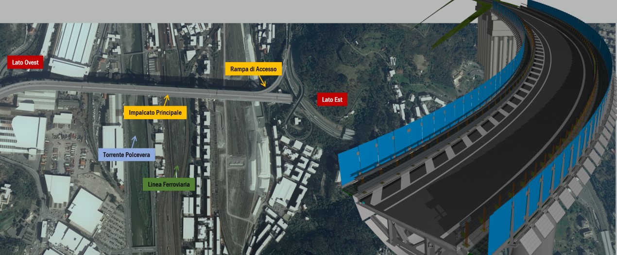
The viaduct over the Polcevera River represents a fundamental point for the connections and transport of Genoa, Liguria and of the Italian economy, constituting the terminal section of the A10 freeway limited, on the east side, by the junction with the A7 (Named 'Genoa Ovest') and, on the west side, by the tunnel embankments leading to the junction named 'Aeroporto'.
The executive project, carried out in record time, provided for the construction of the new infrastructure on the same layout of the old Morandi Bridge, with the necessary regulatory adjustments to the section of the deck and the radii of curvature of the interchanges and entries.
.jpg)
Based on the architectural design developed by the Renzo Piano firm, the bridge will comprise reinforced concrete piers with an elliptical cross-section positioned at constant 50 m intervals, except for three spans – the ones actually crossing over the Polcevera river – and the two adjacent ones, for which the C/C distance rises to 100 m. The main deck will consist of a continuous beam 1,067.17 m long overall consisting of a total of 19 bays.
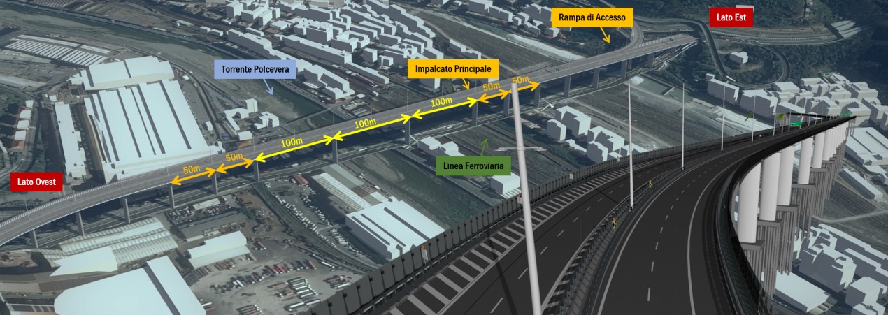
To this deck is structurally connected a steel/concrete 3-span slab 109.91 m long overall. The piers are to be made of reinforced concrete, with constant cross-section for their full height.
The viaduct will feature considerable technological contents in order to enhance the work’s architectural style and its environmental sustainability in terms of energy consumption and will be made so as to ensure very high levels of road traffic safety and maximum durability of the structures and systems.
In the executive design phase, Italferr implemented the BIM (Building Information Modelling) model of the viaduct so as to guarantee very high design standards based on the following principles:
| Application of BIM methodology to the process of coordinating the activities by exploiting the potential of a CDE (Common Data Environment) capable of managing the flow of interdisciplinary data and of guaranteeing their uniqueness and traceability, valid for infrastructure type projects. |
| Definition of the contexts and procedures to be adopted in the course of the design activity to create a Federated Model of the entire infrastructure, extending the modelling activity to all key disciplines and integrating, where possible, the design contents relating to the other disciplines via the use of hyper-models (2D drawings, numerical data, etc.). |
| Orientation and structuring of the work contexts, defining responsibilities, organization and regulations of reference. |
| Definition of the standards, templates and base criteria for the models to be followed throughout the entire design phase, also with a view to using them in the subsequent phases. |
| Identification of the models’ characteristics with a view to aggregating them in specific information tools made to detect clashes and check parameters (Model and Code Checking). |
| Identification of the models’ characteristics with a view to aggregating them in specific time simulation tools (4D model). |
| Identification of the models’ characteristics with a view to aggregating them in specific information tools made to communicate with the various parties involved in the process (Display Models, Production of Visual Outputs such as pictures and videos, Reporting). |
| Production of an information model that can be used as base for the subsequent construction, operation and maintenance phases of the structure. |
Before proceeding with the modelling activities and its components, an Information Management Plan (pGI in Italian) was prepared in order to establish from the start the operational methods and contents of the BIM information model for the Polcevera Viaduct. Subsequently, in order to boost data and information exchange between the various parties involved, a common data environment was prepared in which a structure of worksheets was organized, so that each discipline could have its own workspace.
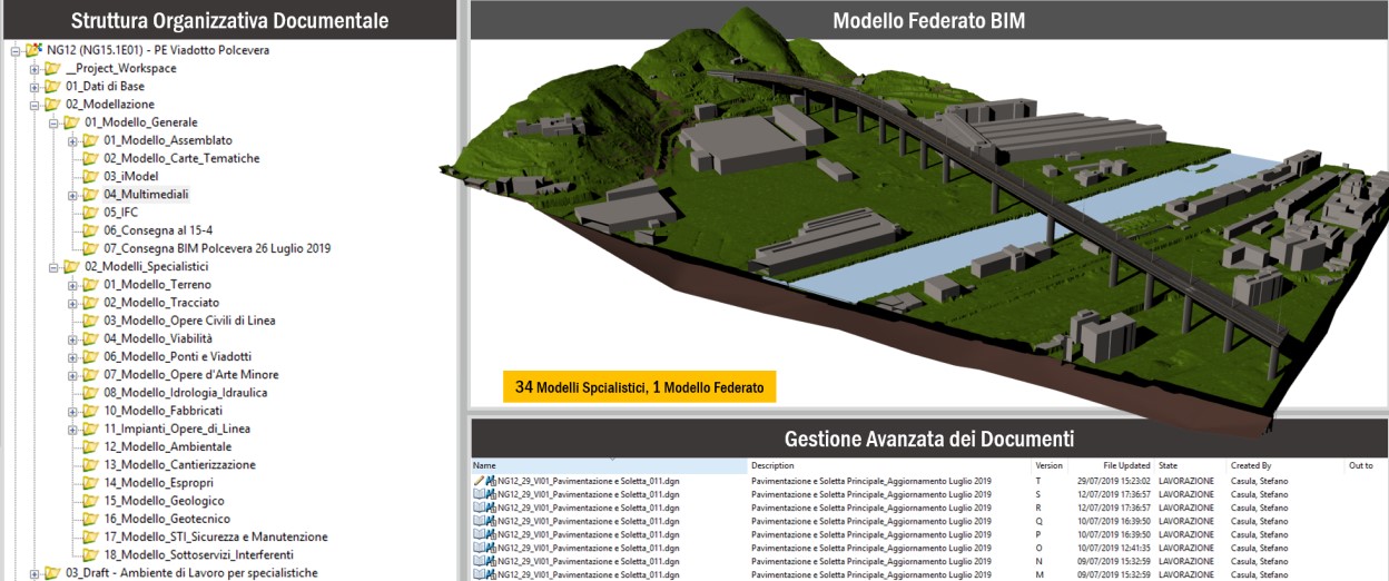
The structuring of the common data environment for the BIM model of the new Polcevera Viaduct was organised to foresee the assembly of many models coming from the various specialised divisions:
Digital model of the Tyrrhenian Sea: triangulated model obtained by post-processing the point cloud dataset obtained via Lidar imaging
Digital model of the Rail Route: digital model of the planimetric and altimetric alignment of the route
Digital model of the new road system: digital model of the road data package as well as of the signalling elements and safety devices
Digital model of the Civil Engineering Works: digital model of the steel and concrete structures
Digital model of the Mechanical Installations
Digital model of the Electrical Installations.
Following a preliminary survey activity via aerial flights equipped with laser scanners, a process of skimming and triangulation of the point cloud was initiated so that the context in which to operate could be digitally reconstructed. The digital model of the terrain alone was then enriched with numerous details and information through the manipulation and insertion of shape files or specially prepared three-dimensional models. To increase the detail of information obtainable from the digital terrain model, the Digital Context thus developed was further supplemented by draping the orthophotos.
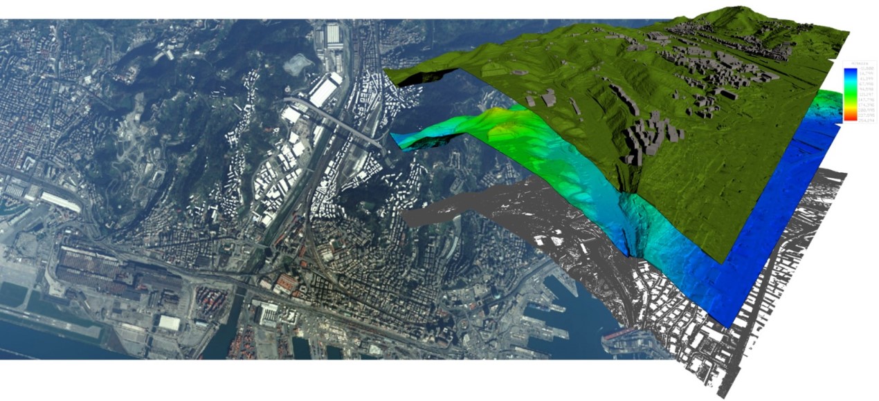
Together with the digital terrain model, by triangulating the data from the field surveys, the three-dimensional bed-rock surface was developed. This was useful for the exact verification of the depth of the foundation piles of the new viaduct.
The plotting activity was supported by a "criteria-based design" system that constrains design choices in compliance with specific regulatory standards. The result is an intelligent, highly parametric-looking 3D polyline capable of adapting to sudden changes, complete with information about the geometric data of the route.
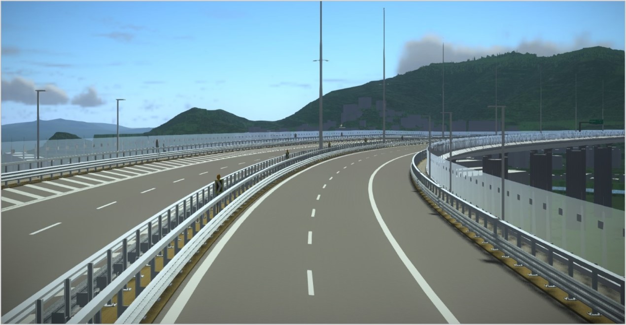
Having defined the itinerary in space, an activity was initiated to produce the library of parametric templates, i.e., type sections capable of changing their geometric configuration consistently with the constraints imposed by the digital model of the route. The creation of the templates made it possible to generate guiding paths along which to place parametric objects and components (e.g., guardrails, signals, etc.). Similarly, the generation of auxiliary surfaces ensured the correct projection of horizontal signage elements along the entire route.
The generation of the three-dimensional solid model of the roads made it possible to manage on the same software environment, and therefore with the same format, the huge amount of data and information that characterises the model of the new road system.
Considering the tight timeline for project definition, it was necessary to set up a structural BIM model (concrete elements and metal deck) capable of updating rapidly and consistently with continuous design changes.
The model of the concrete works was developed by positioning each component in a specific coordinate tern of the modelling space read automatically via programming scripts that would promote interoperability between different software environments. With the input data entered, the process generated different solutions of concrete structures, both in terms of positioning and of geometric configuration.
As regards the metal structures, from the design point of view it was necessary to change the geometry of the diaphragms of the deck to accommodate the changes in elevation imposed by the transverse rotation of the road platform. In addition to handling the transverse rotation of the metal deck, and consequently the geometric variation of all the metal components that depend on it, we proceeded by setting shape parameters that would allow vary, along with the route, the radii of the tri-centre that define the shape of the lower part of the viaduct to which the casing was welded.
This was achieved through component-based parametric modelling and by exploiting a computational modelling process based on code strings and nodes; scripts were developed aimed at optimising and automating manual processes that traditionally would have been very time-consuming.
Having defined the component library via the scripts, the assembly phase of the model was started with the possibility of dynamically managing its parametric content. The scripts are linked to a spreadsheet containing all the basic information needed to define the model. By acting point by point on the individual cell, it was possible to automatically update the model without having to manually act on the modelling. The production of parametric elements with a marked versatility made it possible to obtain a model that was capable of quickly incorporating any changes and updating itself accordingly.
Once the geometries and overall dimensions of each component of the deck were defined, it was possible to provide system designers with a three-dimensional support on which to operate a much more accurate verification of the important technological content with which the viaduct is equipped.
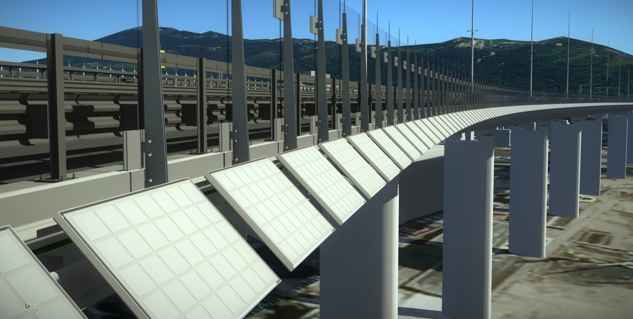
In order to enhance the special architectural value of the viaduct, the design of the electrical and lighting systems was made with equipment not found commercially but rather with special products. In the BIM model, it was necessary to create from scratch families of special products in order to integrate them with the structures. This resulted in being able to visualise the appearance, colour and technical characteristics. Some examples are the scenic lighting fixtures running beneath the edge of the viaduct whose peculiarity is that they can be maintained from the service walkway; the street lighting fixtures that have their power supplies and diagnostics at the base of the poles and not at the lamp edge; and the truncated cone weather detection rods installed on the uprights of the glass barriers.
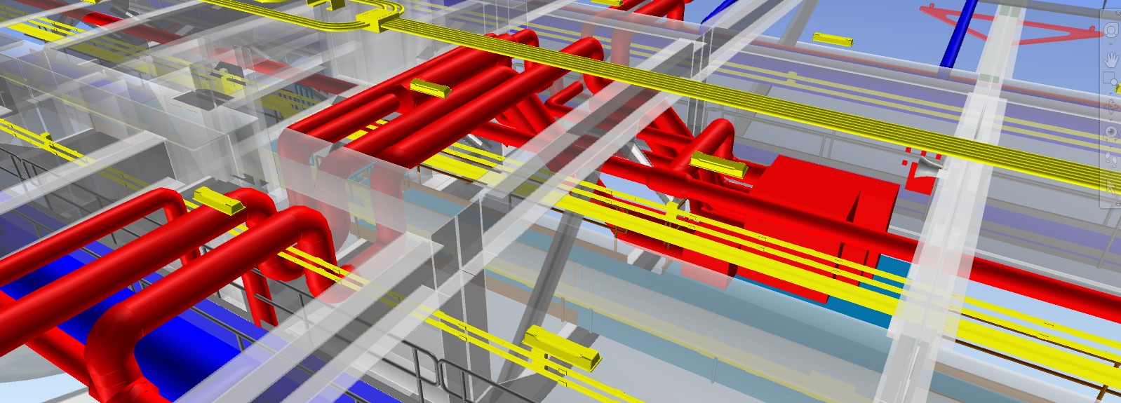
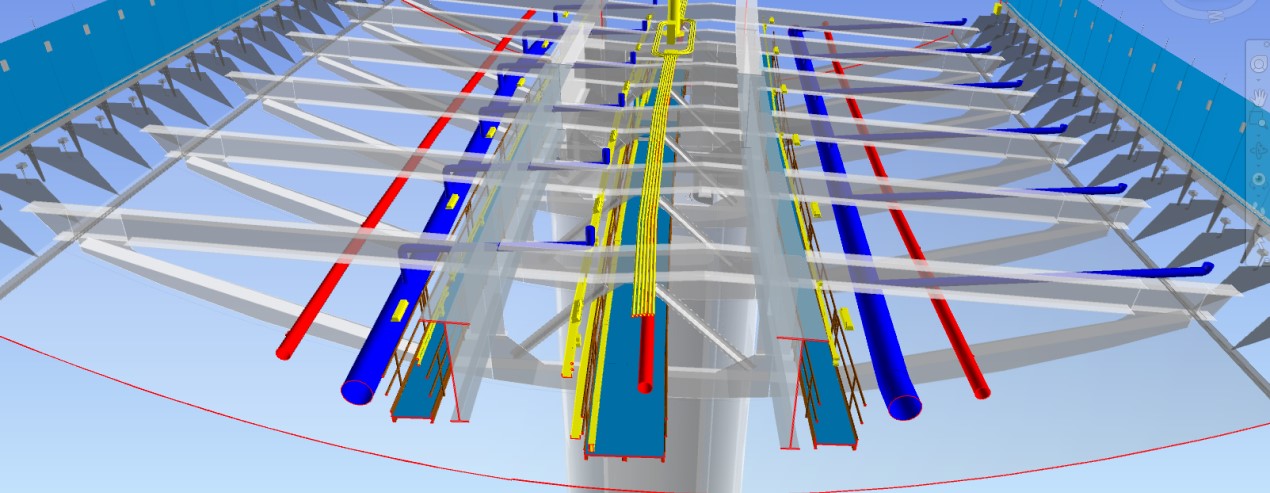
The advantage of having a BIM model was that it was possible to verify the compatibility between the numerous installations coming from the different technological disciplines and the civil engineering works, with particular reference to the confined spaces, such as the passages at the diaphragms reinforcing the deck. It was also possible to precisely determine the location of equipment, its supports and special pieces for anchoring to structures, with regard to non-straight profiles. Examples include the electrified busbar ducts feeding the electrical devices inside the deck for which the exact bending radii, changes of direction and expansion joints were defined, as well as the air diffusion channels inside the caisson.
The BIM model also supported the verification of maintenance operations and the disassembly, moving, and reassembly of equipment. This verification mainly involved the dehumidification machines. Through this verification, the internal passages within the caisson were also optimised and the supply and handling of the machines were defined. In order to minimise openings and interference, a machine type was chosen that would allow the disassembly of the fans, as well as the design of a mobile support that would allow the machine to be moved using the special travel guides provided inside the caisson.
The ability to coordinate and control three-dimensional data and geometries allowed the clear and unambiguous transfer of information to those who then put in place the complex structure of the viaduct. With this in mind, the clash control activity and the parametric verifications conducted on the model at the different stages of updating the individual components gave the work added value in terms of consistency and constructability.
The federation of numerous specialised models and the information each one brings with it has made it possible to obtain a digital twin of the work populated with the artwork and technological installations, thus having one shared environment complete with all its parts. The completeness of the federated model is achieved not only through correct and detailed three-dimensional modelling but especially by inserting and structuring within the model itself the "information" as design parameters and/or as hyperlinks.
The possibility of connecting the BIM model to the works program made it possible to dynamically visualise the evolution of the project in its various construction phases.
The goal was to produce an information model that could form the basis for the subsequent phases of construction and operation, complete with all the information useful for organising maintenance. The achievement of this objective made it possible to put into operation an infrastructure in which the BIM model represents the link between an initial, time-limited phase of design and definition of the structure and the certainly more relevant subsequent phases of operation and management.